loading

19+ years of experience - Comprehensive solutions supplier for mixing and packaging of powder and granular materials.

Continuous mixer 1
Continuous mixer 2
Continuous mixer 3
Continuous mixer 4
Continuous mixer 5
Continuous mixer 1
Continuous mixer 2
Continuous mixer 3
Continuous mixer 4
Continuous mixer 5

Continuous mixer

High efficiency: The continuous mixer achieves an uninterrupted mixing process through continuous feeding and discharging. Its mixing uniformity can reach 95%-99%, and its energy consumption is 20%-30% lower than that of intermittent equipment, which significantly improves production efficiency.

Continuity: The continuous mixer is continuous in loading, stirring and discharging, and is suitable for large-scale projects. Its feeding system usually adopts a screw conveyor or a belt conveyor, and the discharging system is controlled by a valve or a gate to ensure continuous in and out of materials.

Stability: The continuous mixer has high stability and is suitable for large-scale projects. Its stirring mechanism is driven by an electric motor, and the power is transmitted to the stirring shaft through a reducer, ensuring the stability and uniformity of the mixing process.

Energy saving: The continuous mixer has high mixing uniformity and low energy consumption. Compared with intermittent equipment, its energy consumption can be reduced by 20%-30%, further reducing production costs.

    oops...!

    no product data.

    Go to homepage

    Product Description

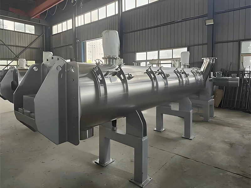
    Continuous mixer is a highly efficient mixing equipment, widely used in chemical, pharmaceutical, food, building materials and other industries. Its main feature is that different materials are continuously input into the equipment according to the set ratio.


    The residence time of the materials in the cylinder is controlled by adjusting the speed of the conveying equipment, the speed of the mixer and the discharge speed. Under the action of the stirring element, the ideal mixing effect and continuous discharge are achieved. The mixing method is suitable for large-scale production.


    Important note: Equipment selection is a relatively important link. Please provide detailed information about the materials and process arrangements as much as possible so that our professionals can provide you with high-quality technical services.

    undefined

    Working Principle

    Continuous mixer 7
    01
    Feeding System
    - Raw materials are continuously fed into the mixer through multiple feeding ports. The feeding ports are usually located at the top or side of the mixer and can be equipped with metering devices as needed to ensure the precise proportion of raw materials.
    - The feeding system can be manually or automatically controlled to meet different production needs. In some advanced systems, automatic control can also be performed through PLC to improve the accuracy and efficiency of feeding.
    Continuous mixer 8
    02
    Mixing Chamber
    - The mixing chamber is the core part of the continuous mixer and is usually made of high-strength stainless steel or other corrosion-resistant materials. The chamber is equipped with special stirring blades or paddles, which are designed to generate strong vortex and shear force.
    - The structural design inside the chamber enables the materials to be fully dispersed and mixed during the mixing process to avoid agglomeration and dead corners. This design ensures the uniform distribution of materials throughout the chamber.
    3 (6)
    03
    Mixing Mechanism
    - The mixing mechanism is driven by an electric motor, which transmits power to the mixing shaft through a reducer. Multiple sets of stirring blades are installed on the mixing shaft, which push the materials to move axially during rotation.
    - Under the action of the mixing blades, the material moves back and forth along the length of the mixing chamber and is mixed in the radial direction. This dual movement allows the material to be fully mixed in a short time.
    5 (6)
    04
    Mixing process
    - When the material enters the mixing chamber, the mixing blade pushes it to one end of the mixing chamber and remixes it at the other end. This continuous pushing and pulling back process causes the material to tumble and mix continuously in the mixing chamber.
    - Due to the design of the mixing blades, the material not only moves in the axial direction, but also is subjected to shear force in the radial direction, further improving the uniformity of the mixing.
    2 (8)
    05
    Discharging system
    - After the mixing is completed, the material is continuously discharged through the discharging port. The discharging port is usually located at the bottom or side of the mixer and can be controlled by a valve or gate to achieve continuous discharging.
    - The discharging system can also be equipped with a screen or filter to ensure the quality of the final product. In addition, the discharging process can also be precisely controlled by an automated control system to improve the continuity and stability of production.
    1 (8)
    06
    Control system
    - Continuous mixers are usually equipped with advanced control systems that can achieve precise control of parameters such as feed rate, stirring speed, mixing time, etc. The control system can be a PLC (Programmable Logic Controller) or a touch screen interface for easy operation and monitoring.
    - The control system can also record and store production data to facilitate subsequent quality management and process optimization.
    undefined
    undefined

    1. Motor, reducer (transmission part) 2. Coupling 3. Main shaft 4. Mixing blades (paddles, coulters)

    5. Observation port  6. Feed port  7. Discharge port  8. Exhaust and dust removal port  9. Base

    Discharge Port Configuration and Sealing Solutions

    To meet diverse process layout requirements, the discharge port of the dual-axis gravity-free mixer can be equipped with either a spherical powder valve or a plum-blossom staggered valve:

    Spherical Powder Valve

    Features a protruding spherical surface that conforms to the curved base of the mixing chamber, minimizing dead zones and residue.
    Enables a large-diameter discharge opening for efficient material flow.
    Provides excellent sealing performance for powders, liquids, and even under vacuum conditions.

    Continuous mixer 15

    Plum-Blossom Staggered Valve

    Designed for simplicity and precise control over discharge speed.
    Can be combined with a long spiral bottom support to stabilize material flow.
    Ideal for applications requiring adjustable discharge rates.

    Continuous mixer 16

    Valve Actuation Options

    Manual, Pneumatic, Electric.

    Continuous mixer 17

    Sealing Systems

    Standard Packing Seal ,Skeleton Seal, Mechanical Seal.

    Continuous mixer 18

    Drive System Configuration

    The dual-axis gravity-free mixer is equipped with drive units of varying capacities, power ratings, and output speeds, tailored to material properties, startup methods, and mixing requirements. Due to the intermeshing relationship of the internal blades, the dual-axis drive system must possess synchronization capabilities. Four drive configurations are available for different operational needs:

    Dual Gearbox Synchronized Combination

     Features two interconnected gearboxes for precise synchronization, ideal for high-torque applications.

    Continuous mixer 19

    Single Gearbox Dual-Output Design

     Utilizes a single gearbox with dual output shafts to drive both axes, offering compactness and cost efficiency.

    Continuous mixer 20

    Dual Planetary Gear Synchronized System

     Employs planetary gear mechanisms for high-precision synchronization and load distribution, suited for heavy-duty mixing.

    Continuous mixer 21

    Bridge Sprocket-Chain Drive

     A chain-and-sprocket linkage system for economical synchronization in moderate-load scenarios.

    Continuous mixer 22

    Internal structure diagram

    12
    12
    13
    13
    14
    14
    15
    15
    里面配图 (6)
    里面配图 (6)
    里面配图 (1)
    里面配图 (1)
    里面配图 (7)
    里面配图 (7)
    里面配图 (8)
    里面配图 (8)

    Features

    The single-axis plowshare continuous mixer is mainly based on mixing and supplemented by conveying. Its special internal structure can adapt to the feeding speed of materials within a certain range to achieve the corresponding production output. At the same time, it can also fully mix the materials in a large range to ensure the mixing uniformity. Combined with the uniform feeding equipment, it ensures the consistency and stability of the output material products.

    The twin-shaft paddle continuous mixer maximizes output and has a more intense stirring effect to disperse materials. The twin-shaft meshing space can evenly diffuse or extrude materials and can adapt to special materials such as fiber mixtures and granular materials.

    里面配图 (2)
    里面配图 (2)
    里面配图 (3)
    里面配图 (3)
    里面配图 (4)
    里面配图 (4)
    里面配图 (5)
    里面配图 (5)

    The dual-axis gravity-free mixer can be equipped with various add-on components to meet specific industrial and process needs, including:

    Process-Specific Configurations: Vacuum or Pressurized Operation: Customized for vacuum or pressurized environments to handle sensitive, reactive, or volatile materials.

    Heating/Cooling Systems: Integrated with circulating medium jackets or steam coil jackets for precise temperature control during mixing.

    Material-Specific Enhancements: Specialized Coatings: Anti-corrosion, anti-adhesion, or metal-isolating coatings to protect against aggressive, sticky, or reactive materials.

    Wear-Resistant Mixing Screws: Screws reinforced with overlay welding of wear-resistant alloys for prolonged service life in abrasive applications.

    Liquid Dispersion System: Liquid Spray Module: A pressure-fed spray system (comprising a pressure source, liquid reservoir, and spray nozzles) ensures uniform dispersion of small liquid volumes into bulk materials, enhancing homogeneity and preventing localized clumping.

    Thermal Management: Jacketed Designs: Maintain consistent thermal conditions for heat-sensitive or exothermic reactions, ensuring stable mixing performance. 

    13 (4)
    13 (4)
    14 (4)
    14 (4)
    15 (4)
    15 (4)
    16 (4)
    16 (4)

    Can be equipped with a variety of components

    Specifications

    Effective volume

    Maximum batch output

    Speed

    Power

    Size(mm)

    LXC-500

    100-250

    2-6

    7.5

    3200*1100*1200

    800

    LXC-1000

    200-500

    5-15

    11

    3800*1200*1350

    1200

    LXC-2500

    500-1250

    10-30

    22

    4600*1600*1680

    1600

    LXC-4000

    800-2000

    20-60

    37

    5000*1800*1860

    2600

    LXC-6000

    1200-3000

    30-100

    45

    6000*2350*2150

    3500

    LXC-10000

    2000-5000

    50-150

    75

    6600*2600*2400

    5500

    LXC-15000

    3000-7500

    80-200

    110

    7000*2900*2650

    8000

    Solution summary

    1: Use ton bags of raw materials, crane hoisting, and direct feeding with dust collector;

    2: Set up a multi-layer platform, manually unpack bags and feed, and use a ton belt packaging machine after mixing and discharging;

    3: Simple use of mixing equipment, direct feeding and direct discharge, and configure forklift loading and unloading;

    4: Use a manual feeding platform, spiral lift the materials into the finished product warehouse after mixing, and connect the packaging equipment below;

    5: Use vacuum feeding method, feed on the ground, and use a ton belt packaging machine after mixing and discharging;

    6: Multi-stage vacuum feeding and transportation, after mixing and storage, packaging;

    7: Multi-layer operating table design, freight elevator feeding, feeding, warehousing, mixing, storage, packaging, integrated tower structure;

    8: Use bucket elevator to feed, mix, store, and package;

    9: Vacuum feeder feeding, mixing, warehousing, packaging, upper and lower integrated structure;

    10: Manual feeding, mixing, warehousing, packaging, upper and lower integrated structure.

    方案汇总 拷贝2

    Product case

    案例
    案例
    发货照片 (3)
    Shipping photos
    发货照片 (1)
    发货照片 (4)
    发货照片 (2)

    Good reasons for working with us

    图片1 拷贝
    1. Customer feedback
    图片2 拷贝
    2. Delivery to customer site
    图片3 拷贝
    3. Installation and debugging process
    图片4 拷贝
    4. Installation flow chart
    图片5 拷贝
    5. Company production strength
    图片6 拷贝
    6. Company production ability
    Feel free to Contact with us

    After 19 years of accumulation and exploration, our team will contribute to the mixed industry with professionalism and ability. We believe that anything is possible through cooperation and enthusiastic service to customers.

    Related Products
    no data
    Ready to work with us ?
    Contact Us
    Copyright © 2025 Zhengzhou CSP Machinery Co.,Ltd. | Sitemap
    Customer service
    detect